Controlling the oil sealing surfaces of rotating shafts is critical to preventing oil leaks. Often this surface is turned on a lathe, which can result in the shaft pumping oil at the seal. Here we will see how a laser can be used to measure the “lead” of the machined surface to prevent oil leaks.
Optimet produces laser scanning devices and here we will see one employed for crankshaft oil hole and lead measurement.
Optimet’s proprietary laser technology is used here for:
· Measurement of ground or undercut (rolled) crankshaft fillets
· Measurement of oil hole geometries
· A need for increased detail on journal surfaces (straightness and profile)
The statement that there is “no good solution” for these issues encompasses a couple of possibilities. Perhaps there is no current technology that addresses these concerns, or maybe the solution is not widely known to the automotive and diesel industries. To date, it appears that no provider of metrology equipment has answered these challenges to the satisfaction of my customers, so I searched for another technology that could do the job.
Because new technologies often require in-field development time to “get the bugs out”, finding a solution that has already been proven in production is preferred. I’m pleased to say that I found an existing, patented technology, which I believe can provide answers for the challenges noted above. This technology comes in the form of a non-contact point sensor system made by Optimet.
In case you’ve never heard of Optimet, they are part of the Ophir Photonics Group, a Newport company. Newport is in turn owned by MKS Instruments and I suspect you’ve heard of them.
Technology:
Where non-contact measurement systems are concerned, it is generally accepted that holography provides an advantage in depth of field, over conventional optical systems. With classical holography, a hologram is created by recording an interference pattern formed between an object beam and a reference beam using a coherent light source. The two beams propagate at the same velocity (same refractive index), but follow different geometric paths. This means that when overlapped, the phase difference between the two beams depends only on the geometric path difference. This phase difference is responsible for the creation of a measurable interference pattern that can later be used to reconstruct the original light field.
Optimet’s sensors use a patented non-contact technology called Conoscopic Holography, the principle of which is illustrated here:
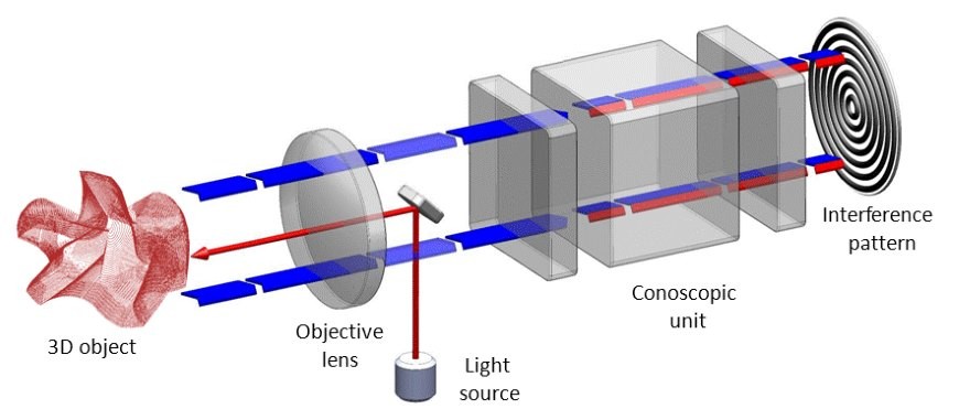
A light beam that traverses an optically anisotropic crystal is split into two beams that share the same geometric path but have orthogonal polarization modes. The refractive indices of these two beams generally differ from each other, so that after the two beams exit the crystal, an interference pattern is generated. The features of the pattern depend on the distance from the light’s source. Since both beams propagate through the same geometric path, conoscopic holography is highly stable in comparison to methods that rely on interferometry-based measurement techniques.
The Optimet sensor emits an eye-safe laser beam, which is focused by an objective lens, onto the subject of the scan. Part of the scattered light travels back from the subject into the sensor and enters the conoscopic unit that contains the optically anisotropic crystal. The resulting interference pattern is detected, and signal processing algorithms are then used to retrieve the distance information from the measured data. Measurement results are stored as 2-dimensional (2D) or 3-dimensional (3D) point data, depending on the customer’s needs and objectives.
Measurement Results:
Optimet lists many applications for this sensor on their website, including measurement of turbine and turbocharger blades, gears, transmission shafts, and other industrial components. For this article, Optimet provided me with data recorded from an automotive crankshaft journal. The surface of the pin journal was scanned from cheek to cheek, including the rolled undercuts and the oil hole. A Newport scanning table was used to position the part relative to the scanner.
An Optimet ConoPoint 10 HD sensor w/ 50mm lens performed two scans on the bearing surface. First, a low-speed, high-resolution scan was conducted to demonstrate resolution. Then, a faster scan was conducted at a lower resolution. The faster scan would be suitable for audit inspections during production, with the slower scan used in R&D. Here is a video clip of the data being recorded:
(This video shows the test fixture and fast scan)
Two scans were performed at the same location on the part. The only difference between the two scans was the point spacing.
Scan 1 :
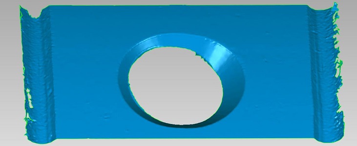
This scan was recorded at X and Y point spacing of 30um x 30um (0.030mm). The time to scan the area for maximum detail was 8 minutes (suitable for R&D use).
The Optimet output data (2D or 3D) can be processed by various software solutions offered through Optimet and other companies. The measurements that can be derived from the data are too extensive to list in the scope of this article. However, an example of what is possible can be seen in the following picture.
This picture shows data recorded from the surface of the journal. In the center is the oil hole, showing the measured angles of the chamfers from the surface of the bearing. The curved areas closer to the edges of the picture show the rolled undercut radii (.001 represents 1mm). Based on these results, this author believes that similar measurements could be made on ground radius fillets, such as those found on a diesel crankshaft.
Scan 2:
Scan 1 illustrates the high level of detail available from the Optimet unit, provided time is not a factor. However, high-density detail is not always required. In these instances, a faster scan, which still provides useful data, but in a fraction of the time, can be employed.
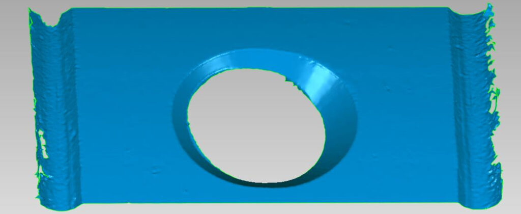
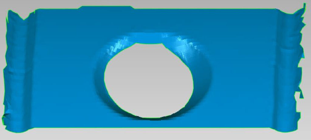
In this second scan, a Y point spacing of 50um, along with an X point spacing of 300um is employed. This reduces scan time to 36 seconds (suitable for production) while still providing useful data on the bearing surface at twice the density of some tactile crankshaft gage systems.
In this image, the data spacing is wider and the oil hole appears to contain steps (bands) in the data. This is because the space between scans is filled in with similar data to construct the 3D image. This does not represent a loss of accuracy, however, the data density itself is lower.
(Note: 1.0 represents 1mm in this picture). The two scans performed by Optimet, represent two examples of the different scan detail available. Both the number of points in the line and the spacing between lines are user defined.
(This video shows the test fixture and a slower, more detailed scan)
These are samples of the information that can be gleaned from the data but you can contact Optimet with your specific requirements. I was pleasantly surprised at the resolution of the data and think that this system could also be employed to look at journal straightness and surface form over the entire width of the journal. The tactile gages currently available, while providing good detail of the bearing surface, fall short at the transition to the oil hole and leave much of the journal surface unmeasured. The Optimet system is capable of higher data density than any of the tactile systems I am aware of.
The measurement solution shown in the videos and used for the test was comprised of:
- A Newport Custom scanning system employing:
- 300mm x 300mm linear stages
- X and Y 0.3um resolution
and an Optimet ConoPoint 10 HD sensor w/ 50mm lens:
- Accuracy 2.5um
- Measurement Range 2mm
- Standoff 42mm
Software:
Optimet wisely chose to provide their data sets in an open source format, so end users can choose a new software package that fits their needs, or possibly use the one they already have. They also offer a software developer kit, so that their sensors can be incorporated on other gauging solutions and machinery. Here are a few of the third-party software solutions that can analyze point cloud data from the Optimet sensor:
I have varying degrees of experience with these software products, but at least one, Digital Surf, allows for macros that can be employed in production environments. Once the calculation is in place, the machine operator needs only execute the analysis to get fast and repeatable results. Optimet’s support staff can help you get started with the solution that best fits your application.
In my opinion, when a metrology company allows third-party access to its measurement data it provides some key advantages over internal software development:
- The metrology company can focus on its core competency; the sensors and machines that make the actual measurements.
- A dedicated software company can often revise and improve the user software faster than a company that “also writes software”.
- More options and user interfaces become available, allowing the customer to find something that best suits their application and their staff’s capabilities.
I’ve previously suggested that the builders of Cylindrical Coordinate Measuring Machines and Roundness equipment could benefit from a third-party software solution and I am pleased to see that the Optimet sensor has this option available.
A Key Advantage of Optimet Technology:
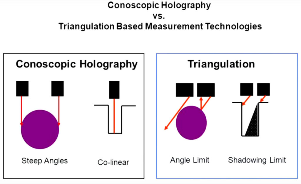
The sensors built by Optimet use a collinear laser beam and sensor. The beam goes out and returns on the same axis, which gives a specific advantage over laser triangulation systems. With laser triangulation, the laser and sensor form two corners of a triangle; the subject of the scan forms the third. Because of this, the beam may miss the inside edge of a feature that has some depth to it (shown in the “shadowing limit” illustration). A collinear system gives a significant advantage for steep angles and features like oil holes, over systems where the beam approaches at an angle. The Optimet sensor can handle a grazing incidence of up to +/- 80 degrees, a significant advantage over laser triangulation.
Measurement ranges from tens of microns to tens of centimeters can be achieved with the same sensor by swapping removable objective lenses. The sensors are surface and material quasi-independent, allowing measurement on surfaces ranging from highly reflective to roughly textured. This allows for the bearing surface and surrounding casting to be measured with the same Optimet sensor.
Working closely with an Indiana-based machine integrator allows Optimet to provide turn-key solutions to their customers. Additionally, they offer several periscope solutions that allow for measurements to be made on a variety of parts, without the need to alter or destroy parts to execute the measurement. Optimet also makes a scanning sensor solution which eliminates the need for a moving table, depending upon the accuracies that are required. That system may be more appropriate for casting surfaces, or non-moving parts.
The Optimet Conopoint sensor used in this test is very affordable, falling under USD $10,000. Final cost of a complete system depends on the customer’s requirements and the degree of integration required. Optimet technology is currently used in over 5000 installations worldwide. The sampling rates (up to 20,000 Hz) are fast enough to collect detailed data even when the target is moving quickly, as shown in this short video:
Future Application Development:
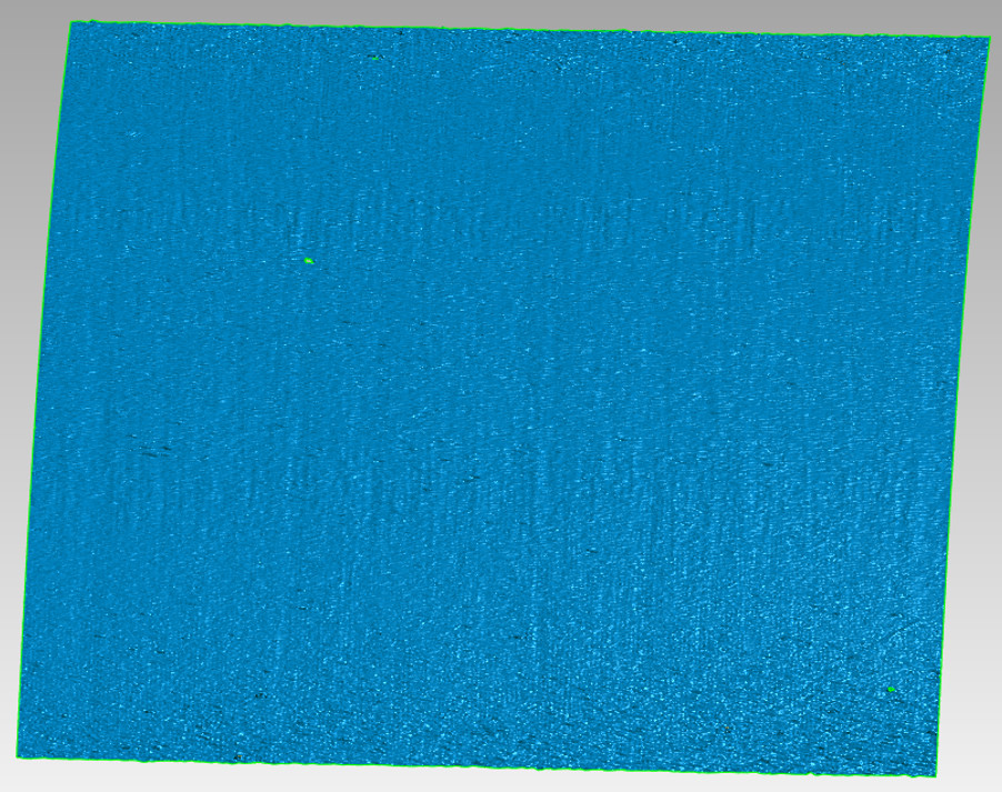
(image of Oil Seal Surface, side-to-side, direction of rotation in the vertical)
To me, the Optimet technology also looks promising for other measurements, such as this crankshaft oil seal surface. However, Optimet was quick to point out that this requires further investigation and no inferences should be made from this image. They noted that the horizontal banding appears to be a measurement artifact and that more testing is required to validate the results. Still, this author sees a potential way to quantify oil sealing surface, as seen in the vertical striations, after more R&D. Perhaps one of the automotive or diesel engine manufacturers will assist Optimet in developing this application.
If this technology looks interesting to you, Optimet has a great video on YouTube that describes it in detail:
Conclusion:
From my perspective, it appears that Optimet’s patented technology can provide many proven application solutions for crankshafts and other automotive parts. In my opinion, the technology is applicable to many other components, in addition to crankshafts. These include camshafts, transmission shafts, engine blocks, pistons, valves, heads, and their mating components.
As is usual in this series, I want to state that I have received no compensation from Optimet, their parent company, or their affiliates. I’m just a measurement geek who’s always on the lookout for new and innovative solutions to my customer’s problems. You can check out their technology yourself, or on their website at Optimet.com, or by emailing them with your application questions at: support@optimet.com
Update 2023: Optimet has since been acquired by MKS Instruments.
Thanks for reading!
This article originally appeared on LinkedIn and was reprinted with permission from the author
